I’ve been wanting to upgrade the stock tail light on my Suzuki GSX650F for some time now. I was hoping an upgrade might precede a quick fender chop to rid the bike of that hideous plastic dragging the aesthetics down. The deed has finally been done (both the tail light upgrade AND the fender chop). Here’s how:
UPGRADING THE GSX650F TAIL LIGHT:
Tools involved:
- Metric Hex Keys (Allen keys/wrenches)
- #2 Phillips Screwdriver
- Precision screwdriver (flat or philips) – or other precision tool
- (Optional) [Blade] Cable splices X 2
- Used for integrated turn signals
- Allows for use of stock and integrated signals
- Pliers or Crimpers
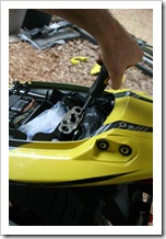 (1) Step one involves removing the seat by unlocking the ‘trunk’. Once it’s off, remove the actual lock mechanism (2 X Philips screws/bolts) so the rear cowling can be separated from the fender without the lock cable tethering it.
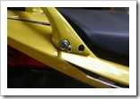 (2) Next, remove the two bolts [on each side] keeping the rear handle attached to the frame. Carefully lift the handle up and set it aside.
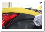 (3) Using a small, precision screwdriver (or other instrument) press in the black push buttons on each of the 4 X plastic rivots holding the fender to the rear cowling. After pushing each ‘button,’ carefully pull out each plastic rivot and set in a safe place.
 (4) The cowling should be free to remove, though you’ll still need to disconnect the modular electrical connector attached to the brake/tail light when you have access to it.
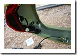 (5) Set the rear cowling on a soft surface (to avoid scratches) and grab a #2 Philips screwdriver to remove the two screws holding the OEM tail light fixture in place. Once removed, set your OEM tail light aside for storage.
(6) Grab your after-market LED tail light and mount it on the rear cowling using the original screws that held your OEM light in place. Take the cowling back over to the bike and connect the modular plug to your after-market light. If you have no intention of wiring your integrated LED turn signals, your finished! Replace the parts in the reverse order described above.
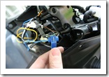 (7) If you’re planning on using your new, integrated turn signals (with or without your stock signals), then grab some coffee & keep moving on… Using the wiring method described here, you do NOT need to cut/sever any electrical wires to use the integrated turn signals. Grab some quick-splice blade connectors and slide your bike’s positive (+) lead (not the black/white stripe wire – that’s the ground) from each turn signal into the slot provided. Depending on what model of LED tail light you’re
 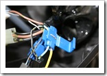 using, you may or may not need to splice the ground (-) lead of each turn signal. In my case, the after-market tail light wiring diagram indicated the integrated turn signals were grounded through the modular cable connector, so no ground splice required =)
(8) Once you’ve got the turn signal positive lead (+) in position, grab the wire from the tail light’s integrated turn signal and slide it into the other (outside) wire slot. Next, crimp the blade onto both wires and fold over the plastic splice cover. Repeat the same steps for the other turn signal.
Note that if you’re using BOTH sets of turn signals (i.e. the stock signals & the integrated signals) you’re flash rate will be normal since the load will be nearly the same as stock. However, if you’re not using the stock signals you may want to install inline load resistors to slow the flash/blink rate. It’s personal preference and I chose to leave mine at a rapid flash/blink rate to attract the attention of careless drivers…
Now that you have a new tail light [with integrated turn signals] it’s on the fender mod!



Share this post
Twitter
Google+
Facebook
Reddit
LinkedIn
StumbleUpon
Pinterest
Email